This circuit shows the connector at the display end, and the ultimate destinations for the active wires.
 |
This is the Selector Switch. I have used this trick before-using an analog voltage for a digital value to save on wiring. It relies on the inherent matching of resistor packs.
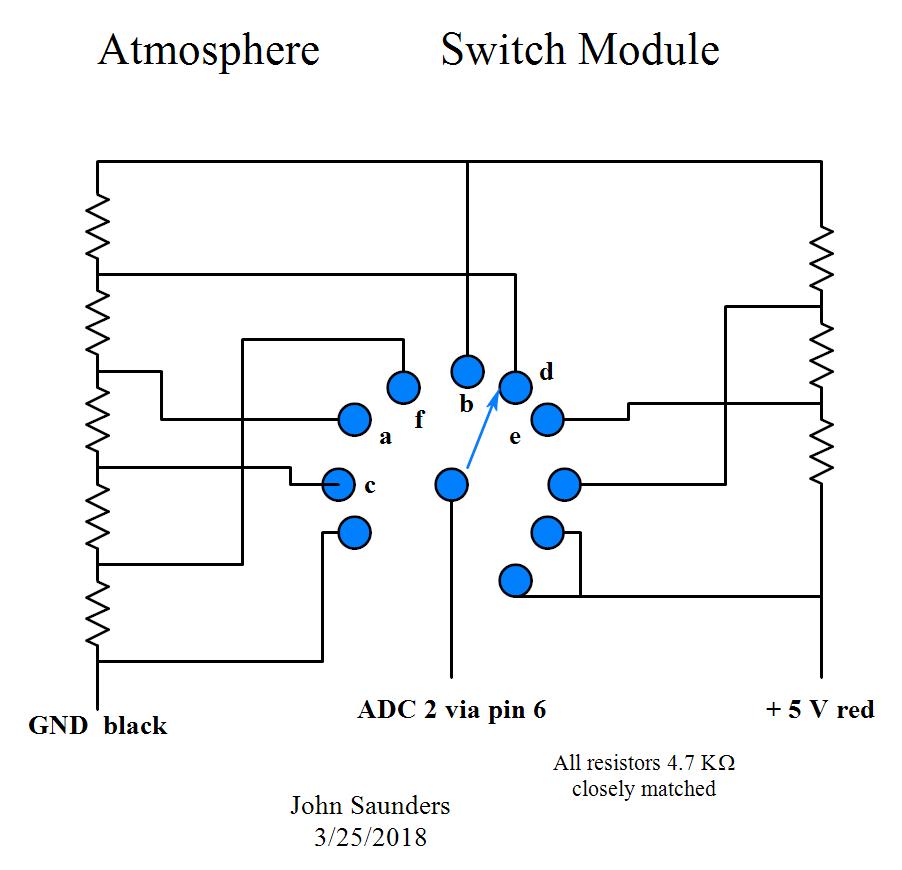 |
This is the power supply. It is recycled with modifications. It is connected to the Sensor Board via its own attached 7-conductor cable.
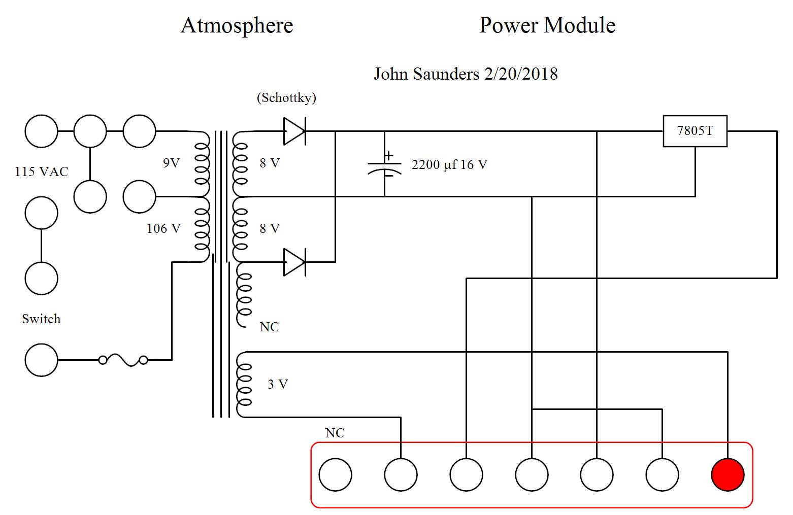 |
| In addition the opto-interrupter and the programming connector are chassis-mounted. The latter's cable may be plugged into either board, as required. |