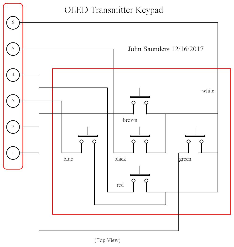
Care was taken in the layout to avoid soldering where the board touches the keypad shell.
The keypad connector on the right aligns with the resistor pack and the Picaxe to avoid wires.
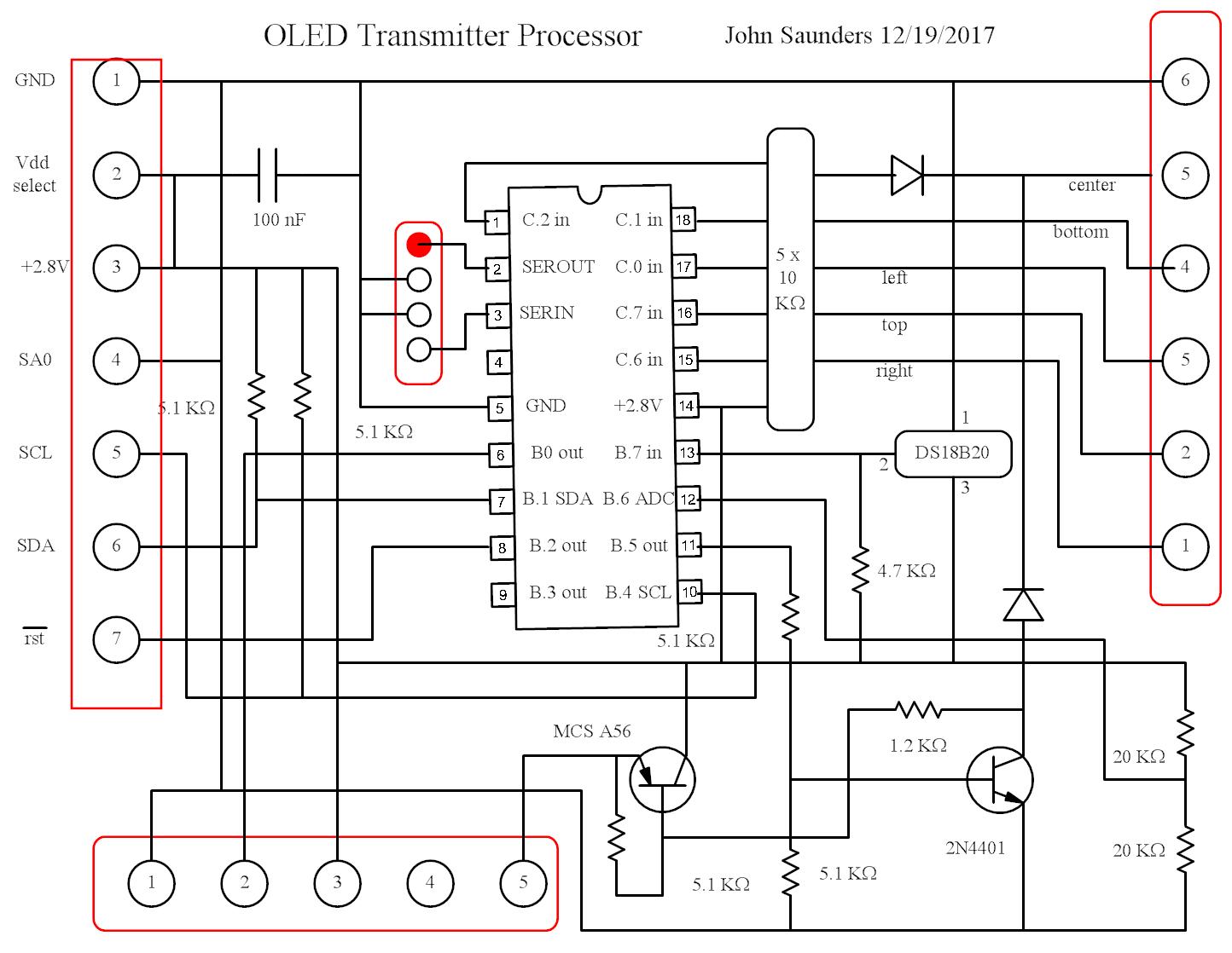
The transistor circuit allows the center button to turn on the power while retaining its transmit function.
The circuit maintains power via computer control and is open-circuit when the computer relinquishes control.
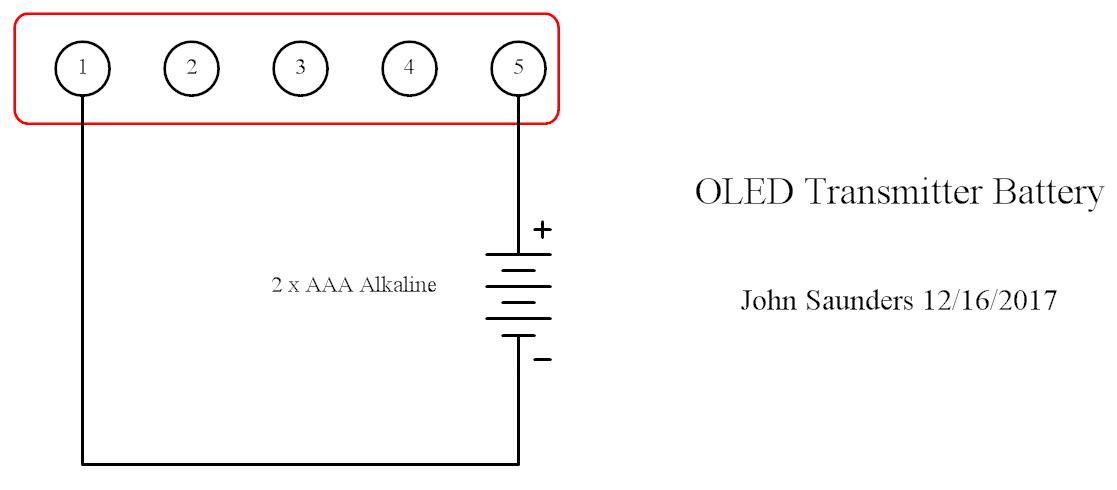
The board area under the battery module contains only wires and 1/8 watt resistors.
As is usual with stripline almost all jumper wires are perpendicular to the traces.
No changes were made to this excellent unit which was intended to be part of a servicing tool for RV generators.
It only draws current when keyed on.
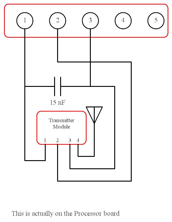
This plugs into the lower connector, the transmitter is soldered into the main board.