A handheld universal control with an LCD display

Although I previously made a universal controller, the OLED Control, it was daunting to add the Tower Display commands to it since its memory was full.
This one seemed easy, since I has bought cheaply a standard Arduino mated to a shield with a 2x16 backlit LCD and 6 push-buttons. However it was a cheap knockoff and it failed. It was replaced by a genuine Arduino.
Actually, since making this project I have re-programmed the OLED Control to include the Tower Display, but it entailed a new approach and a substantial re-write of the code.
Since this project uses an Arduino, there is plenty of memory, but the fixed strings had to be placed in the program memory, a nuisance.
Since four of the push-buttons mimic the arrow-button rosette of the OLED Control, the code uses the same human interface. The left button mimics its central button, but could not be used to turn on the power because of the hardware design of the shield.
Instead a roller-ball tilt sensor is used, The project goes off when turned upside-down
The up and down buttons select one of five areas of the house, or one of four displays which is identified on the top row. The left and right buttons select the channel and on or off command of that receiver for action, or a page in a display. These are displayed on the lower row.
Another problem is that the stabdby current is too high, so the interval to recharge the battery is too infrequent. Also the buttons are tiny,so I do not like this device!

Here are the circuit diagrams

Here is the code

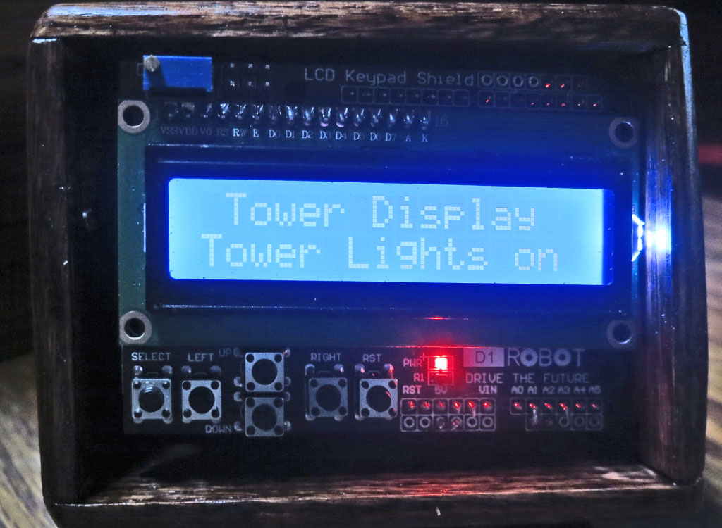
This is a view of the shield, which is on top. It is plugged into a standard Arduino. Under that is an assembly, shown below.
All three are fastened together and slide into a cubical wooden case from the top.

This is the lower assembly.
It comprises five sub-assemplies:
1. A rechargable 750 MAH Li Ion battery. This is wrapped in brown tape.
2. In the upper left is a green module which is the charge controller for the battery. It's micro-USB connector is accessable through a hole in the case.
3. On the lower left is a module containing the tilt sensor. It controls power via an enable input tp the DC-DC converter..
4. On the right is a boost DC-DC converter which provides a regulated 5V to all circuits.
5) A circuit board holds all together and contains the transmitter module and two interface transistors needed by inadequacies in the Arduino.

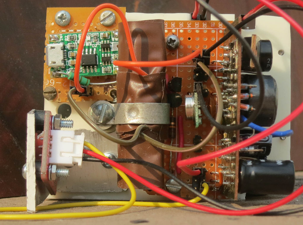
All interconnections are by jumper wires.